House Electrical Wiring Layout
Complete DIY House Electrical Work
The planning of the house electrical wiring layout plan is an important step in the interior design process. A detailed electrical layout plan is worked out as a blueprint for the entire electrical system of the house.
The electrical wiring layout plan is a graphical representation of the electrical wiring system. The layout plan includes lights, fans, air conditioners, a hot water geyser, a refrigerator, room heaters, a television, and other electrical gadgets plugged into the system.
The electrical wiring layout diagram helps the architects and interior designers plan the illumination for various interior spaces. It also helps to precisely calculate the demand for electricity for the house.

The estimated demand for electricity is a crucial factor that defines the technical specifications for the electrical wiring. During the planning process, the interior designer or architect has to first define the number of electrical gadgets to be installed as per the functional needs.
Based on the wattage requirements of these gadgets, the peak estimated demand for electricity is calculated. The choice of the electrical connection type ( Single Phase Or Three Phase ) depends upon the electric load estimation.
The next step in the planning of the electrical layout involves finalizing the location of the various electrical switch boards and the electrical points needed for various gadgets to be plugged in.
In this tutorial, you will learn how to design the electrical wiring layout for a house during the interior design planning process, how to decide the technical specifications for the electrical wires, switches, and other electrical material used for the electrical wiring.
House Electrical Wiring Layout
What Is Electrical Wiring Layout Plan ?
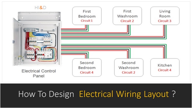
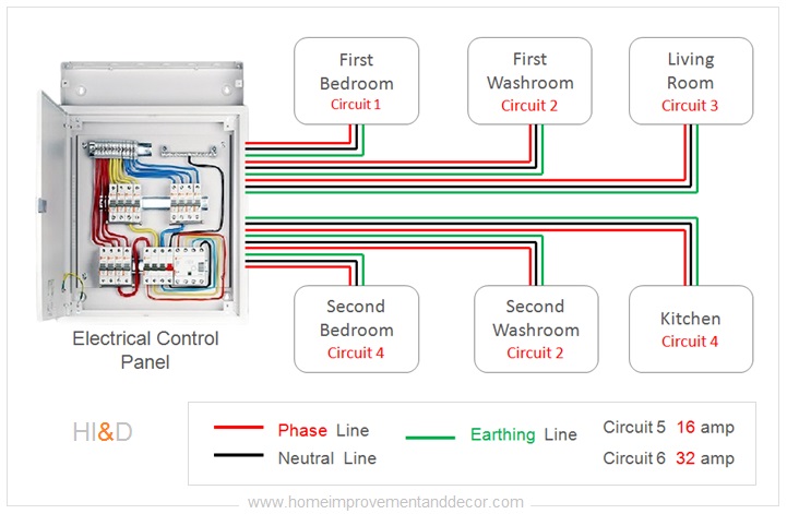
The house electrical wiring layout defines the electrical connections between the different rooms and the main electrical power supply through a control panel. The electrical wiring layout is planned in such a way that the electrical wires can easily support the designated electrical load.
The house electrical wiring layout diagram is prepared, which indicates the electrical connection between the electrical boards in all the rooms and the main electric control panel.
The home electrical wiring layout basically defines how different rooms are connected to the main electrical power supply through a control panel..
The home electrical wiring layout depends upon the type of the electrical connection ( Single Phase Or Three Phase Connection).
The electrical wiring layout planning is an important step in order to ensure the functional convenience and the safety of the users.
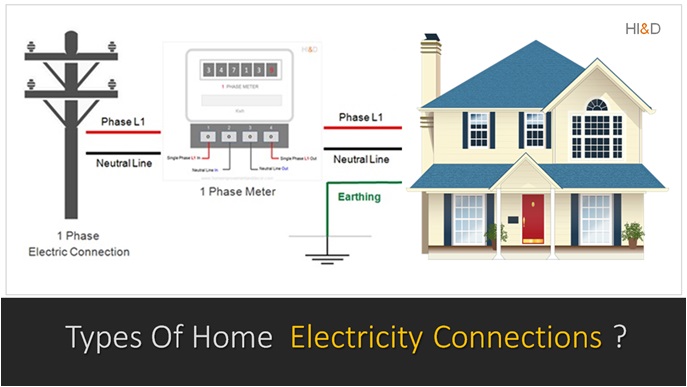
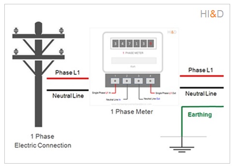
Your house is connected to the electrical service lines located outside your house . These electric service lines can be either overhead cables or underground lines.
The electric power supply lines are connected to your home through a electrical control panel also referred as distribution box that works as a junction box common for the entire house electrical system.
House Electrical Wiring Layout
How To Plan The Electrical Wiring Layout ?
The entire house electrical work project can be grouped into two steps. The first step is to plan the electric layout. And the next step is to execute the actual wiring work as per the layout plan. The standard process to plan the house electric wiring layout includes the following steps:
- Identify requirements for electrical points in each room.
- Decide the rated capacity for each point in a room.
- Calculate the electrical load for each room.
- Mark the location of the electrical switch boards for each room.
- Divide the entire electric load into number of circuits.
- Decide the rated capacity for the electrical wires.
- Decide the size of the main electrical control panel.
Single Phase Electric Connection
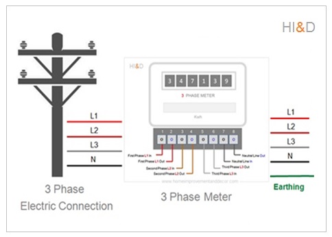
Three Phase Electric Connection
The first step in planning the electric layout for a house is to identify the requirements of the electrical points needed in various rooms. The electrical load capacity of the points depends upon the intended use of the points for connecting various electrical gadgets.
For example , the standard bedroom will have two points for light bulbs , one ceiling fan , two light points for lights on the bed side table, one power socket ( 30 amp plus ) for one AC unit , one power socket for room heater, one power socket to operate the vacuum cleaner and four more sockets ( 5 amp ) to connect other small wattage gadgets.
Similarly , the electric load calculation is done for all the room. The summation of the electric loads would be equal to the total electric load. Based on the total electrical load requirements, the electricity connection type is selected which is either a single phase or three phase connection.
House Electrical Wiring Layout
What Is Electrical Point ?
The term electrical point is a general term used to refer to a one specific application of the electric supply. For example, on your electric switch board in a room , you will find some switches and plug points.
Each electric switch present on the board in a room is used to switch on or off a specific electric device such as light or fan. This one single electric connection on the board is referred as one single point. The electric board can have many such points.
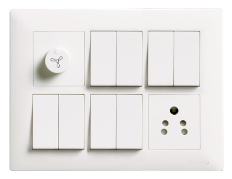
Types Of Electrical Points
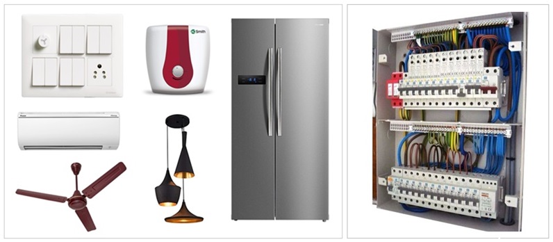
Different types of electrical sockets and electric switches are provided on the electric board. Each of these socket and electric points can support only the gadgets with specified load limit.
For example, for normal gadgets such as fan, lights, and electric sockets for mobile charging or other such low wattage application, the electrical sockets with 5 ampere rating is considered to be safe.
Similarly , the higher wattage gadgets such as electric iron, geyser ( up to 3 kilowatt ), mixer unit, washing machine, room heater, air conditioner up to 1 ton capacity and other such electrical gadgets needs socket with 15 ampere and above rating is considered safe.
For very high wattage gadgets ( above 3 kilowatts ) such as electric water geyser , room heater , air conditioner above to 1.5 ton capacity and other such electric gadgets needs socket with 30 ampere and above rating is considered safe.
House Electrical Wiring Layout
How To Calculate Electrical Wire Rating ?
Electrical Cable Rating Table
After finalizing the house electrical wiring layout, the next step is to determine the electrical current rated capacity of the electrical cables. Different types of electrical cables are used depending upon the electrical load.
The current rated capacity of the cables depends upon the cable gauge specified in square millimeter (sq.mm) and other specifications. Depending upon the electrical load calculation for each room (electrical circuit) suitable wire must be used. Similarly, the selection of the circuit brakers installed in the control also depends upon the rated capacity of the cable used and load calculation.
Cable rating table indicates the cable cross section area , rated current carrying capacity and the recommended circuit braker.
Cable Cross Section Area | Cable Current Rating | Circuit Braker MCB |
1.5 Sq.mm | 7.9 - 15.9 Ampere | 8 Ampere |
2.5 Sq.mm | 15.9 - 22 Ampere | 15 Ampere |
4 Sq.mm | 22 - 30 Ampere | 20 Ampere |
6 Sq.mm | 30 - 39 Ampere | 30 Ampere |
10 Sq.mm | 39 - 54 Ampere | 40 Ampere |
16 Sq.mm | 39 - 54 Ampere | 60 Ampere |
25 Sq.mm | 39 - 54 Ampere | 80 Ampere |
50 Sq.mm | 54 - 72 Ampere | 125 Ampere |
70 Sq.mm | 72 - 93 Ampere | 150 Ampere |
95 Sq.mm | 117 - 141 Ampere | 200 Ampere |
House Electrical Wiring Layout
Electrical Load Calculation
How To Calculate Electrical Load For A Residential House ?
Let us now discuss, how to calculate the load electrical for a house based on which home owner can apply for the suitable electrical connection. Calculating the electrical load for a residential house involves determining the total wattage required to power all electrical appliances and devices within the home.
Here’s a general process to calculate the electrical load:
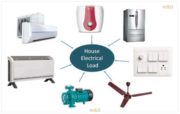
- Identify Electrical Appliances: Make a list of all electrical appliances and devices in the house, including lights, kitchen appliances, heating and cooling systems, entertainment devices, and any other electrical equipment. Make provision for gadgets to be installed in future. For example , you might need installation of air conditioner in all the rooms.
- Determine Power Ratings: Look up the power ratings (in watts) for each appliance. This information is typically found on the appliance’s label or in the user manual. If the power rating is given in volts and amperes, you can calculate the wattage using the formula: Watts = Volts × Amperes.
- Calculate Power Consumption: Multiply the power rating of each appliance by the average number of hours it is used per day. This will give you the daily energy consumption for each appliance in watt-hours (Wh).
- Sum Up Energy Consumption: Add up the energy consumption (in watt-hours) for all appliances to get the total daily energy consumption for the house.
- Convert to Wattage: To calculate the electrical load in terms of wattage, divide the total daily energy consumption (in watt-hours) by the number of hours in a day (typically 24 hours).